- Home
-
Solutions
-
Products
-
SMF Software
- KAI
-
Service & Support
- Global Support
-
About Neotel
- Blog
- Request a Quote
Advanced Ionic Contamination Testing for PCBs and Electronic Components. The NCT delivers precision measurement of ionic contamination levels through both dynamic and static testing methods, fully compliant with IPC-TM-650 standards including R.O.S.E. test and Ion Chromatography.

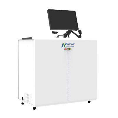
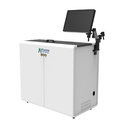
The NCT Neo Cleanliness Tester combines dynamic and static testing methods with high-precision conductivity measurement to deliver reliable ionic contamination analysis for mission-critical electronics.
Ionic contamination is the presence of charged particles (ions) on electronic surfaces that can interfere with proper device functioning. These ions, introduced through dust, moisture, or pollutants, leave residues that can disrupt current flow, cause short circuits, or interfere with sensitive component operations.
Common sources include flux residues from soldering, handling contamination, environmental exposure, and chemical residues from cleaning processes. Even trace amounts of ionic contamination can compromise long-term reliability, particularly in high-density assemblies where conductor spacing is minimal.
Ionic contamination testing is critical for aerospace, automotive, military, and telecommunications industries where electronic reliability is non-negotiable. Contamination-free PCBs are mandatory for conformal coating, epoxy staking, or underfill processes — any ionic residue beneath these protective layers becomes permanently trapped and will eventually cause field failures.
Flux residue is the primary concern in SMT manufacturing. Incomplete cleaning after soldering leaves ionic residues that cause delamination, poor wetting, and electrochemical migration. The NCT detects these residues before they become reliability risks, ensuring every board meets IPC cleanliness specifications before downstream processes.
The NCT supports the complete range of IPC-TM-650 ionic contamination testing methods, from traditional R.O.S.E. testing to advanced ion chromatography preparation.
| Testing Method | IPC TM-650 Reference |
|---|---|
| R.O.S.E. Testing | IPC TM 650 2.3.25 |
| Modified R.O.S.E. Testing | IPC TM 650 2.3.25.1 |
| Ion Chromatography | Ion Chromatography |
| SIR Testing for Materials | IPC TM 650 2.6.3 Series |
| Electromigration Test | IPC TM 650 2.6.14 Series |
The NCT delivers consistent, repeatable results across both dynamic and static testing modes, meeting the demanding requirements of high-reliability electronics manufacturing.
Common questions about ionic contamination testing and the NCT Neo Cleanliness Tester. For further detail, please contact our technical consultants.
Protect your electronics from ionic contamination failures. The NCT Neo Cleanliness Tester delivers IPC-compliant precision testing for the most demanding quality standards.